Surge Protection in Outdoor Lighting: Why Fixtures Fail Early and How to Specify SPDs
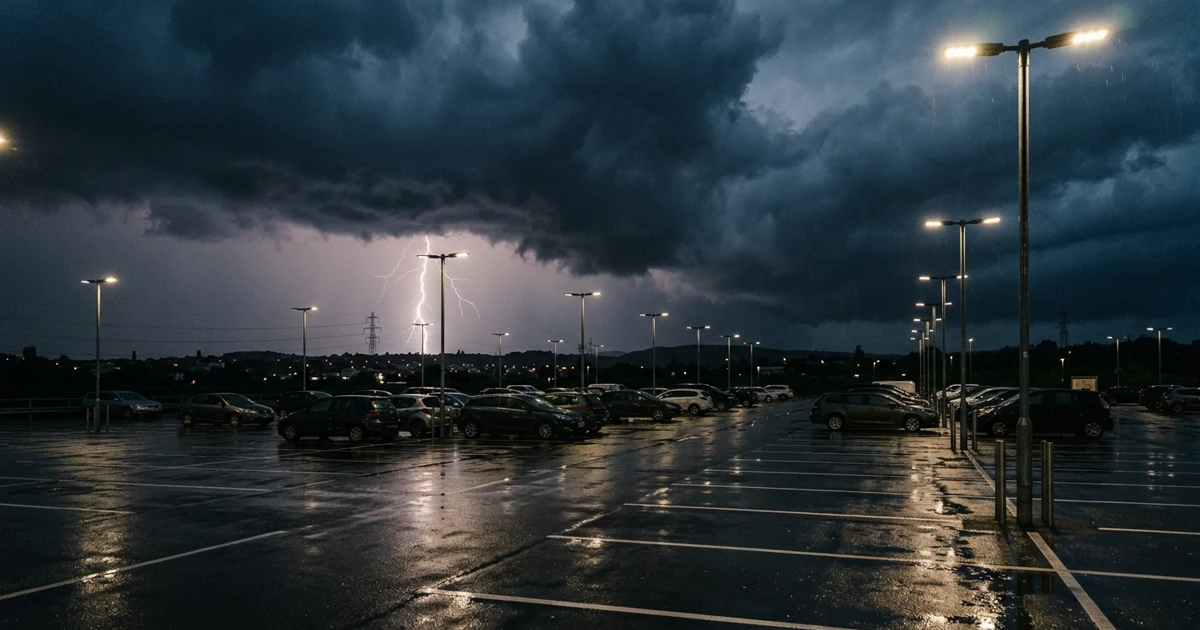
Outdoor LED installations rarely fail the way procurement teams expect them to. The projected failure mode is gradual lumen depreciation — a slow fade toward the L70 point (the hour count at which output falls to 70% of initial lumens) eight or ten years out. The failure mode that actually generates warranty claims is abrupt and early: a batch of car park floodlights goes dark after a summer thunderstorm, or a run of facade fixtures on one feeder stops working in the second year while identical units on another circuit run untouched.
Neither pattern is a lumen maintenance problem. Both are electrical survivability problems, decided by a component that most quotations describe in one unverifiable word: “surge protection: yes.”
This article covers why immunity test levels and installed exposure severities are different quantities that are routinely confused, how to read the surge ratings that carry meaning, and what to require in a specification.
Information in this article is current as of 23 September 2026. Standard editions are cited explicitly; verify against the current edition before writing a specification.
1. What Actually Destroys an Outdoor Fixture
A surge is a transient overvoltage lasting microseconds. Two sources dominate in outdoor lighting.
Indirect lightning. Direct strikes on a luminaire are rare and essentially unprotectable at fixture level. The common event is a strike some distance away that induces a voltage transient onto the supply cabling. Published estimates of annual cloud-to-ground flashes in the United States range from roughly 25 million to 40 million depending on source and method, but the mechanism matters more than the count: outdoor lighting sits on long, exposed feeders that couple these events efficiently.
Utility and load switching. Less dramatic and far more frequent. Capacitor bank switching, transformer operations, and large inductive loads dropping off the same feeder generate transients year-round, in clear weather. These rarely destroy a driver in one event. They degrade the protective components inside it until one ordinary transient finishes the job — which is why failures often cluster in year two or three rather than the first storm.
The distinction that matters for specification is the circulation mode:
- Differential mode — the transient appears between live conductors (line-to-line, or line-to-neutral).
- Common mode — the transient appears between the live conductors and earth.
A fixture protected in only one mode is not protected. Common-mode events are typical of induced lightning transients on earthed poles, and a device configured only across line and neutral will not see them.
2. Immunity Test Levels Are Not Exposure Severities
This is the most costly confusion in outdoor lighting procurement, and it survives because every party’s paperwork is accurate.
The immunity floor has two tiers
Lighting equipment sold into most regulated markets must meet IEC 61547:2020 (third edition, adopted in Europe as EN IEC 61547:2023), the EMC immunity standard for general lighting equipment. Critically, it does not set one surge level for all lighting. The third edition raised levels specifically for road and street lighting equipment — one of the named technical changes relative to the 2009 second edition:
| Equipment class under IEC 61547:2020 | Line-to-line | Line-to-earth |
|---|---|---|
| General lighting equipment | 1 kV | 2 kV |
| Road and street lighting equipment | 2 kV | 4 kV |
These map onto the test levels of IEC 61000-4-5:2014+A1:2017, the underlying surge immunity test method — Level 3 and Level 4 respectively:
| IEC 61000-4-5 test level | Line-to-line | Line-to-earth |
|---|---|---|
| Level 1 | — | 0.5 kV |
| Level 2 | 0.5 kV | 1 kV |
| Level 3 | 1 kV | 2 kV |
| Level 4 | 2 kV | 4 kV |
If a supplier quotes the 1 kV / 2 kV figure for a pole-mounted roadway product, they are citing the general-lighting tier for equipment the current standard places in the higher one. That alone is worth catching.
The exposure severities
Now compare against ANSI C136.2-2023, the roadway and area lighting standard covering dielectric withstand and electrical transient immunity for luminaires and control devices. It defines three transient immunity test severity levels, with application guidance assigning product categories to each:
| Test severity level (ANSI C136.2-2023) | Surge rating | Application guidance |
|---|---|---|
| Typical | 6 kV / 3 kA | Building entrance, building exterior |
| Enhanced | 10 kV / 5 kA | Parking garage, parking lot, tunnel |
| Extreme | 20 kV / 10 kA | Street and roadway, stadium, airport |
A roadway luminaire is expected to qualify at the Extreme level: 20 kV, against a 4 kV immunity floor. That is a factor of five — and the voltage ratio understates the real difference.
Why the voltage ratio understates it
Peak voltage alone does not consume a protective component. Delivered energy does, and energy depends on the source impedance behind the test.
IEC 61000-4-5 uses a combination wave generator with a 2 Ω effective source impedance, adding a 10 Ω resistor for line-to-earth coupling — 12 Ω total. A 4 kV line-to-earth test therefore delivers on the order of 330 A. The ANSI C136.2 severities are quoted as voltage/current pairs, and 20 kV / 10 kA implies a 2 Ω source. That is roughly thirty times the current at five times the voltage.
The practical gap between “meets the immunity standard” and “qualified for an exposed pole” is therefore not a rounding difference. Conformity establishes a floor for equipment on ordinary mains; it was never written as a survivability target for hardware on an exposed outdoor feeder. This is why a conformity mark — CE, UKCA, or the equivalent mark in your market — answers a different question than the one a buyer specifying car park lighting is asking. The correct question is not is it compliant but what severity level is it tested to, and with what device fitted.
3. Reading Surge Specifications That Mean Something
Three standards frameworks appear on datasheets, and they are not interchangeable. Confusing them is how a low-severity component ends up in a high-exposure application.
IEC 61643-11 — what class of SPD it is
The product standard for low-voltage surge protective devices (IEC 61643-11:2011) classifies by test waveform and intended installation point:
| Class I (Type 1) | Class II (Type 2) | Class III (Type 3) | |
|---|---|---|---|
| Test waveform | 10/350 µs | 8/20 µs | Combination wave (1.2/50 µs + 8/20 µs) |
| Key rating | Iimp 12.5–50 kA | In 5–20 kA | Uoc, typically 6–10 kV |
| Installation point | Service entrance | Distribution board | Point of use |
| Protects against | Direct lightning current | Induced surges, switching | Residual transients |
Devices fitted inside luminaires are normally Class II. A Class III point-of-use device cannot substitute for upstream protection, and a fixture-level SPD does not replace protection at the distribution board — they are coordinated stages, not alternatives.
Three parameters deserve attention on the datasheet:
- Up (voltage protection level) — the clamping voltage that actually reaches the driver during a surge. A high surge current rating with a poor Up value protects less than the headline number suggests. Up must sit below the impulse withstand capability of the driver behind it. For Class III devices, read performance from Uoc rather than from an 8/20 µs current figure.
- In (nominal discharge current) — a device must withstand In repeatedly, not once. Because In represents repeat capability while Imax is a single-shot rating, a higher In is the better predictor of service life on a feeder subject to routine switching transients.
- Uc (maximum continuous operating voltage) — must suit local supply conditions. An SPD with Uc too close to nominal voltage ages prematurely.
IEEE C62.41.2 — how severe the location is
Location categories describe the installed environment rather than the device. Category A is well inside a building, Category B is at distribution level, and Category C covers service entrances and outdoor exposed conductors — which is where pole-mounted lighting lives. A device qualified only for a sheltered interior category is not a match for an exposed pole. Note that IEEE C62.41.2-2025 now supersedes the long-current 2002 edition, so confirm which edition a test report refers to.
UL 1449 — safety of the device itself
Where IEC 61643-11 grades performance, UL 1449 (5th edition, 2021) governs what happens when a device fails: abnormal overvoltage behaviour, fire risk, and disconnect provisions. Its type designations describe construction, not only installation location:
- Type 5 covers discrete component surge suppressors — an MOV mounted on a board, or supplied with leads and terminations.
- Type 4 covers component assemblies: one or more Type 5 components together with a disconnect, or a means of complying with the limited current tests.
- Types 1CA, 2CA and 3CA are Type 4 assemblies with short-circuit protection added.
The buyer-facing point is simple: ask which type designation the in-luminaire device carries. A Type 4 assembly includes a disconnect or has passed the limited current tests. A bare Type 5 component has not.
4. Two Misconceptions That Cost Money
“The SPD is rated 20 kV, so the fixture is rated 20 kV.” It is not. The severity level applies to the luminaire tested with the SPD installed, as a coordinated assembly. A device can pass in isolation while the complete fixture fails, because clamping voltage, internal wiring layout, lead length, and driver withstand capability all participate. A component certificate is not a fixture test report. Ask which one you are being shown.
“Surge protection is a one-time purchase.” Metal oxide varistors — the clamping element in most lighting SPDs — degrade cumulatively. Every transient absorbed removes a fraction of remaining capacity. An SPD is a consumable with a service life set by local surge activity, not a permanent component. On a multi-year installation it belongs in the maintenance plan, not only the bill of materials. How you discover it has been consumed is itself a design choice: series-connected devices take the luminaire dark, parallel devices fail silently. The next section covers which to specify where.
5. Failure Behaviour and Serviceability
How an SPD fails matters as much as what it withstands, because it determines whether anyone finds out.
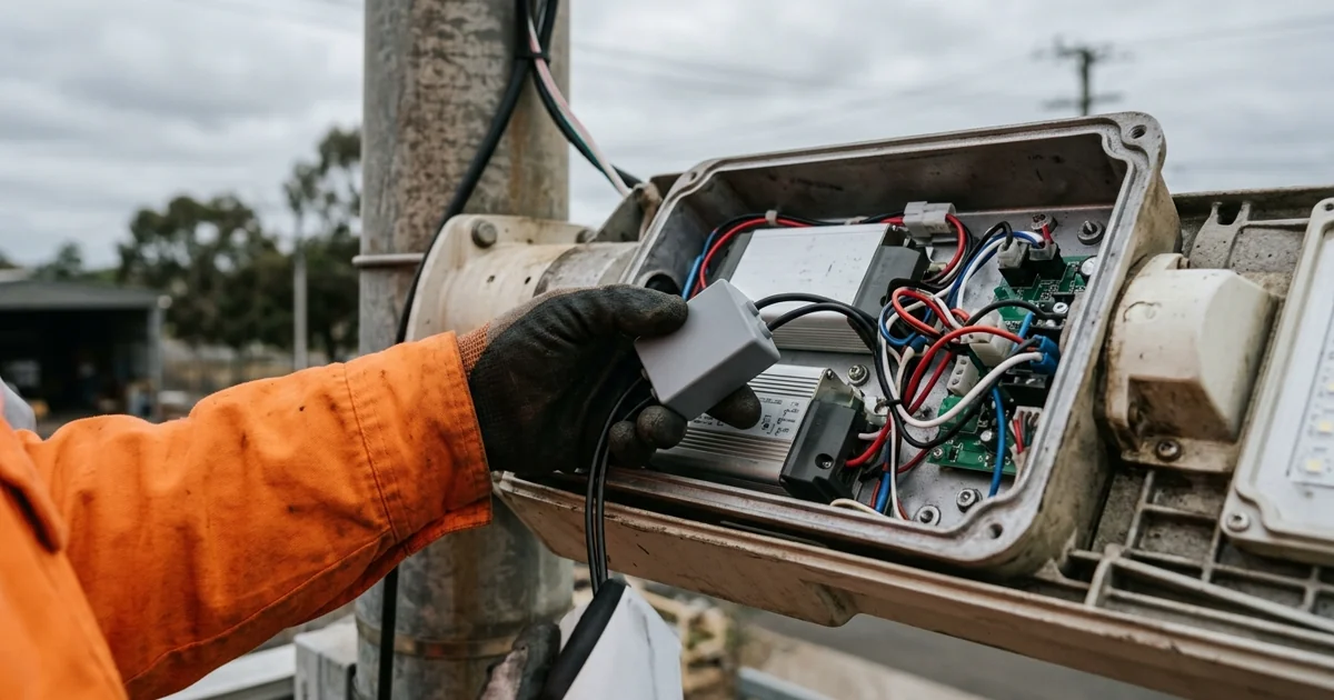
A varistor reaching end of life can go to a low-impedance state and draw sustained current — a thermal and fire risk, which is why protective modules incorporate a thermal disconnect that isolates the varistor when it overheats. Require this as a safety feature, not a premium option.
What happens after that disconnect operates depends on connection topology:
- Parallel-connected SPD. The protective device sits across the supply. When it disconnects, the luminaire keeps running — unprotected. Without an external indicator, nobody knows. The installation continues in a degraded state until the next transient takes out the driver, and the failure is then recorded as a driver fault rather than a surge protection fault.
- Series-connected SPD. The supply passes through the device. When it disconnects, the luminaire goes dark. That is inconvenient and unambiguous: the outage is the indication, and the fixture is never left exposed.
Neither is universally correct. Parallel with a visible status indicator suits installations with regular inspection rounds. Series suits remote or infrequently inspected assets where silent loss of protection is the greater risk. What is not acceptable is leaving the choice undefined and discovering it after a claim.
Serviceability compounds this. An externally mounted, field-replaceable module means a maintenance visit swaps a part. An SPD potted inside a sealed driver compartment means a low-cost consumable condemns the entire fixture. Across a large installation, that decision can outweigh the unit-price difference it was traded against — and it is invisible in a unit price comparison.
6. Specification Checklist
Replace “surge protection: yes” with requirements that can be verified and enforced.
Define the severity level first. State the required level per ANSI C136.2-2023 — Typical, Enhanced, or Extreme — or the equivalent classification used in your market, derived from the installation type. Building exterior, car park, and roadway are three different answers. Applying one uniform level across a mixed project overpays on sheltered locations and underprotects exposed ones.
Confirm which immunity tier applies. For road and street lighting products, confirm the supplier has tested to the road and street lighting levels of IEC 61547:2020 (2 kV line-to-line, 4 kV line-to-earth), not the general lighting levels.
Require fixture-level evidence. Ask for the test report for the luminaire tested with the SPD fitted, not the SPD component certificate alone. If only a component certificate exists, coordinated performance has not been demonstrated.
Require both modes. Confirm protection covers common mode and differential mode, and ask for the Up value in each mode, not only the surge current rating.
Require the full parameter set, with editions. Uc, Up, In, Imax, and the IEC 61643-11 class — plus the edition year of every standard cited. A quoted kV figure alone is not a specification.
Specify failure behaviour and indication. State whether the SPD is series or parallel connected, whether a thermal disconnect is fitted, and how end of life is signalled — indicator, luminaire shutdown, or remote status reporting where a control system is present.
Specify serviceability. Externally accessible and field-replaceable, or not. Get it in writing, with the replacement part reference.
Check the warranty text. Many outdoor luminaire warranties exclude damage from transient overvoltage, lightning, or supply anomalies. Where that exclusion exists, the specification is the only safeguard the buyer has, and its commercial weight rises accordingly.
7. FAQ: Common Questions on Surge Specification
How often should surge protection modules be replaced? There is no fixed interval, because varistor wear depends on the local transient environment rather than elapsed time. This is why end-of-life indication matters more than a replacement schedule: a device with status indication or series shutdown tells you when it has been consumed, while a silent parallel device on a high-activity feeder may have no capacity left long before any calendar-based service date.
Do these considerations apply to low-voltage or DC-powered outdoor lighting? The exposure is the same, but the strategy differs. With a remote driver or DC distribution, the transient can couple onto the secondary wiring as well as the mains side. Specify which ports are protected rather than assuming one mains-side device covers the installation.
Conclusion
Surge performance is one of the few outdoor lighting parameters where a fully compliant product can be a poor fit for its installation, and where the discrepancy is invisible in both the price and the conformity paperwork. The immunity floor for road and street lighting equipment is 2 kV line-to-line and 4 kV line-to-earth; the test severity expected of a roadway luminaire runs to 20 kV at 10 kA, from a far lower source impedance. Closing that gap is a specification decision, not a certification outcome.
The practical shift is small: treat surge protection not as a yes/no attribute but as a rated, tested, serviceable subsystem with a defined severity level, failure behaviour, and replacement path.
Before releasing your next outdoor lighting specification, request the fixture-level surge test report and the SPD replacement procedure from each bidder — and compare what comes back.
Sources
- IEC 61547:2020, Equipment for general lighting purposes — EMC immunity requirements, third edition (adopted as EN IEC 61547:2023). Named technical changes include increased ESD and surge test levels for road and street lighting equipment: general lighting 1 kV line-to-line / 2 kV line-to-earth, road and street lighting 2 kV / 4 kV.
- IEC 61000-4-5:2014+A1:2017, EMC — Part 4-5: Testing and measurement techniques — Surge immunity test (test levels 1–4; combination wave generator, 2 Ω source impedance, 10 Ω added for line-to-earth coupling)
- ANSI C136.2-2023, Roadway and Area Lighting Equipment — Dielectric Withstand and Electrical Transient Immunity Requirements (test severity levels: Typical 6 kV/3 kA, Enhanced 10 kV/5 kA, Extreme 20 kV/10 kA)
- IEC 61643-11:2011, Low-voltage surge protective devices — Part 11: SPDs connected to low-voltage power systems (Class I/II/III test classifications; Uc, Up, In, Imax, Uoc)
- IEEE C62.41.2-2025, Recommended Practice on Characterization of Surges in Low-Voltage (1000 V and Less) AC Power Circuits, superseding C62.41.2-2002 (location categories A, B and C, described in IEEE C62.41.1)
- UL 1449, 5th edition (2021), Standard for Surge Protective Devices (Type 5 discrete components; Type 4 component assemblies; Types 1CA/2CA/3CA)
Next scheduled review: March 2027, or earlier if IEC 61547, IEEE C62.41.2 or ANSI C136.2 is revised.